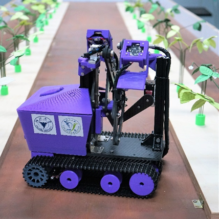
Strawberry Nursery Robot - Mr. Y
A strawberry nursery robot developed by Team Qizhen Lakers from the Agricultural Robotics Club(ARC) of Zhejiang University(ZJU), which is awarded 2nd Place (Best Electronic Presentation) in the Standard Division of the 2021 ASABE Robotics Competition
Member: Yiyuan Lin, Yuliang Zhou, Daoyuan Jin, Xinyue Sun, Yilin Zhang Advisor: Prof. Zunzhong Ye, Yonghua Yu and Huanyu Jiang
ARC (Agricultural Robotics Club) is led by Prof. Zunzhong YE. ARC was established in 2017 and has won numerous achievements in agricultural robotics competitions domestic and international. Its predecessor won the championship in the ASABE (American Society of Agricultural and Biological Engineers) robotics competition in 2016 as the first university outside the United States. Our principles for developing robots are Seeking Truth, Pursuing Innovation, and Giving a Robot a Soul.
Video Presentation
Team Qizhen Lakers- 2nd Place (Best Electronic Presentation) in the 2021 ASABE Robotics Competition
Paper Report
For detailed technical development information, please refer to Report
Definition of Design Objectives and Criteria
The robot to be designed for this competition should have the ability to recognize the white and yellow leaves of strawberry plants and complete the counting display. In order to achieve the goal perfectly, a detailed and specific division was made to complete the task efficiently and accurately. The sub-points are as follows.
- Robot needs to have a navigation function without guidelines.
- Identify white flowers and yellow leaves on each strawberry plant.
- Transfer detection results of individual plants to a server program for scoring and field map generation.
- Minimize the weight of the robot and increase the contact area to reduce the pressure.
- No damage to the plant.
- No human intervention to the robot.
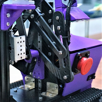
- Have a start button that judges can use to initiate a competition trial and an emergency stop button to fully shut down the entire system.
In the design of robot, we are committed to assure better performance, stronger environmental adaptability, and expandability with more development prospects.
Originality
Originality
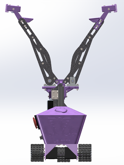
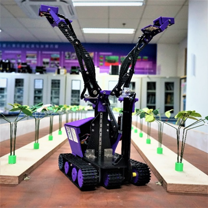
Innovative Linkage Design
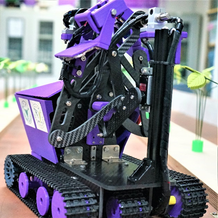
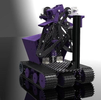
We use the combination mechanism of slider and linkage to realize the full unfolding of double cameras bracket and create the development condition for double sides detection. And the linkage mechanism has strong scalability, which can reach different unfolding results by adding nodes, connecting rods or linkage structures to meet a variety of needs, and can also add end-effectors at the end of the linkage to achieve more functions.
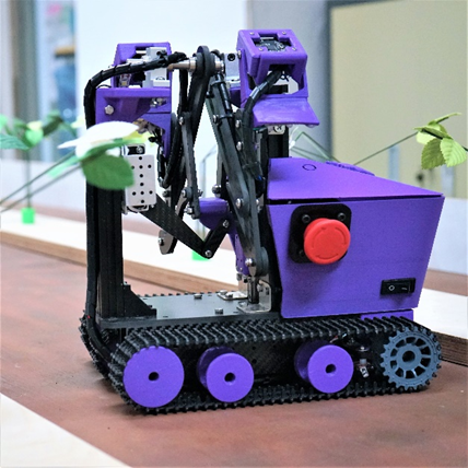
Lower Pressure
We adopt the crawler trolley structure and make the optimal design for the actual production situation of field operation by calculating and selecting the appropriate size of active wheels, tensioning wheels and load-bearing wheels and determining the optimal spacing to share the pressure to the maximum extent and reduce the impact on soil compaction.
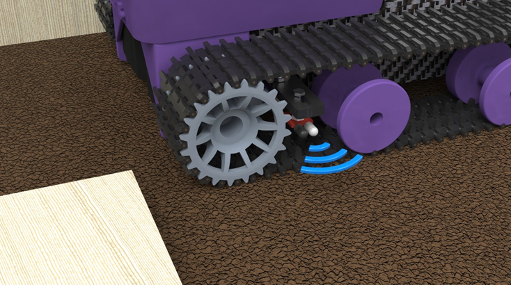
Infrared-Sensor Tracking
Since we make the robot travel between the board where the strawberry plants were placed and the board as the boundary of the field, we only need to install the infrared sensor at a suitable height (That is, slightly below the thickness of the board on which the strawberry plants are placed), adjust the sensitivity of the signal received by the infrared sensor, and keep the robot moving in a straight line in the desired area by making reasonable use of the differential speed rotation of the stepper motor through the signal measured by the infrared sensor.
Supplemental Light Source
By increasing the fill light band, we make the recognition conditions within the controllable range, eliminate the influence caused by different environmental backgrounds, increase the contrast between the recognition target and the background, and make the robot have better self-adaptability.
Multi-threaded Process
We use Raspberry Pi as both processor and control component, and all electronic devices of the robot are controlled through the Raspberry Pi. Calling Python’s multi-process module, 3 processes of Raspberry Pi run simultaneously, thus giving higher performance and increasing working speed. The tasks of motor and servo rotation, simultaneous image processing recognition of cameras on both sides and wireless transmission are realized.
Remote Emergency Brake
Through the wireless transmission module and Bluetooth module of Raspberry Pi, we designed several remote emergency braking solutions. Although there are already both start switch and emergency brake switch on the robot, considering that there are certain safety hazards of actually approaching the brake when an unpredictable emergency occurs, we made a remote emergency brake switch, which is connected to the Bluetooth module, thus controlling the operation of the Raspberry Pi. In addition, using WIFI wireless communication technology, we can access the graphical interface of the Raspberry Pi for operation. Since all the robot components are controlled by the Raspberry Pi, we can stop the operation of the Raspberry Pi at any moment and thus stop the robot operation. Of course, this does not allow the robot to cut off the power supply system, so we designed an emergency brake switch on the robot to directly cut off the power supply.
Hardware Description of the Mechanical Structure
Crawler Structure
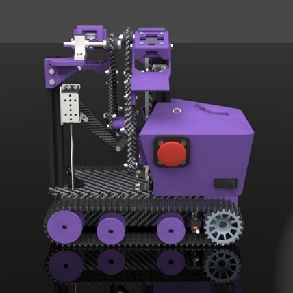
In order to reduce the impact on soil compaction and to allow the robot to adapt to a wider range of road environments, we designed a tracked travel mechanism.
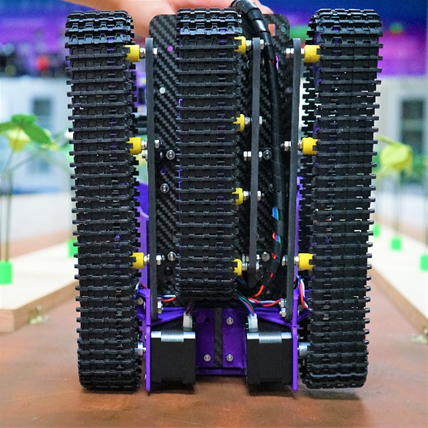
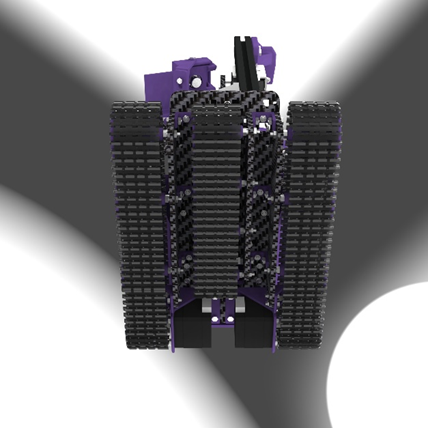
The outer two tracks are long tracks with a ground length of 223.5 mm and a width of 45 mm, equipped with one active wheel, one tensioning wheel and two load-bearing wheels. The middle track is a short track with a ground length of 160 mm and a width of 45 mm, and is equipped with four load-bearing wheels. By reviewing the relevant literature, we calculated the radius and spacing of the active wheel, tensioner wheel and load-bearing wheel. Under the size limitation, we selected the optimal size and spacing.

| Type of wheel | Radius |
|---|---|
| Active wheel | 25.65 mm |
| Tensioning wheel | 26.65 mm |
| Load-bearing wheel | 20.00 mm |
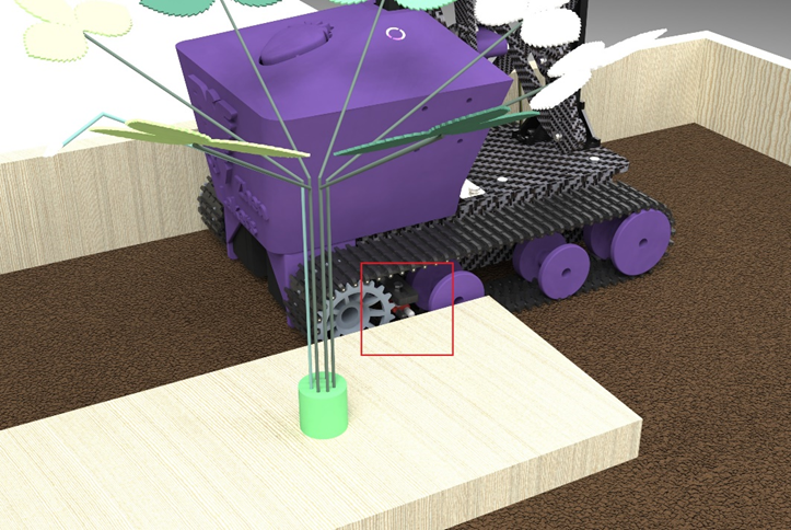
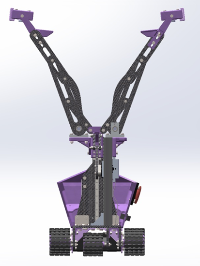
Expanded Mechanical Structure
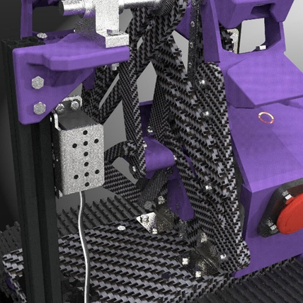
To simplify the actuator, we use a slide rail and a single-degree-of-freedom extension mechanism with multiple links to extend the camera for detection. The multi-stage linkage is articulated by screws and lock nuts, connected to the slide rail by slider connectors, and uses bearings at some of the connections to reduce frictional resistance, and rotates, lifts, and extends under the drive of the servo. As shown in Figure 5-5 and Figure 5-6, with the rational design of 4 connecting rods on each side (8 in total on both sides), we achieved to expand the robot from the initial size of 300 mm × 209.2 mm × 292.5 mm to 300 mm × 440 mm × 528 mm.
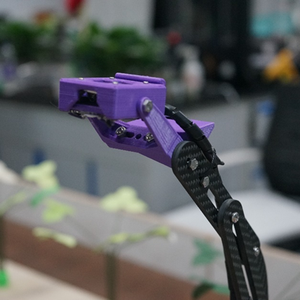
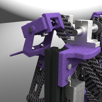
Adjustable Field of View
In order to facilitate the adjustment of the camera view, we designed a camera connector adjustable in angle.
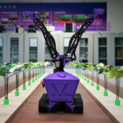
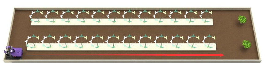
Tracking Design and Walking Route Map
As shown in Figure 7-2, the robot sends and receives the infrared signal reflected back from the wooden board through two infrared sensors installed between the active and load-bearing wheels on the outer track to determine the position of the site it is in, and adjusts its direction by controlling the differential rotation of stepper motors through Raspberry Pi to ensure that the robot can achieve a straight line in the site along the path as shown in Figure 7-3 to provide the best position for detection.
Machine Vision
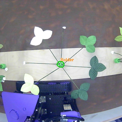
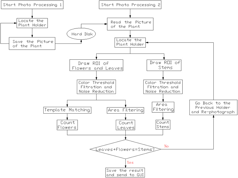
Holder detection
After the robot starts to run, it first identifies the holder. We use the color and shape characteristics of the holder to match the data obtained from the camera, and when the camera moves to the top of the holder, we save the image acquired by the camera instantly for subsequent processing, and get the coordinate information of the holder center.
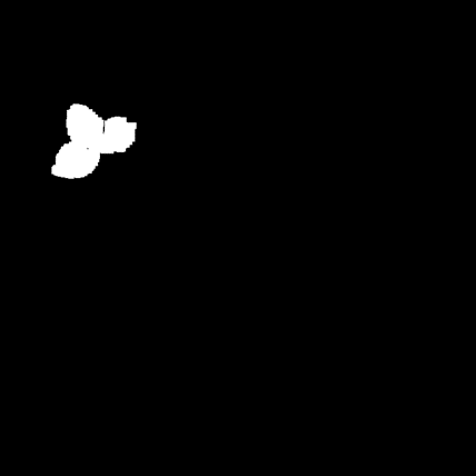
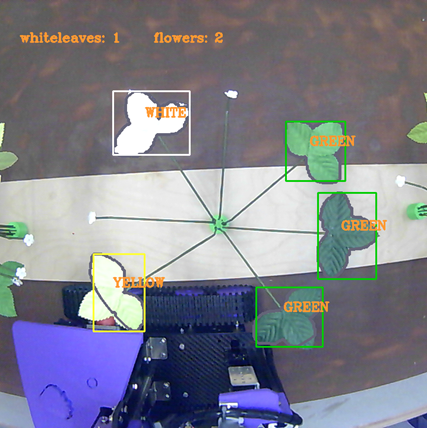
Leaf detection
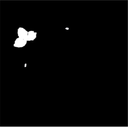
After getting the image directly above the plant, the colors in the image are extracted using the green, yellow and white thresholds, respectively. The filtered images of each color channel are filtered to obtain images with smoother borders, and the area and shape parameters of the continuous areas in them are calculated, while the noisy parts with obviously small areas or narrow shapes are filtered. The image of each color channel is processed as mentioned above to get a grayscale image containing only leaves, and the leaves of each color in it are counted in order to store the number of corresponding color leaves.
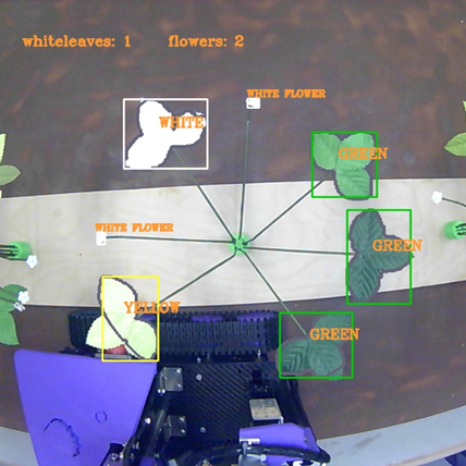
Flower detection
In particular, the results after the white threshold extraction in the previous session are re-processed with filtering and area calculation, and graphical matching is added to obtain the detection results of white flowers.
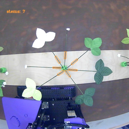
Stem detection
Similarly, we use the characteristic values of stem color to filter specific locations in the image to obtain a grayscale image of the stems for counting the stems.

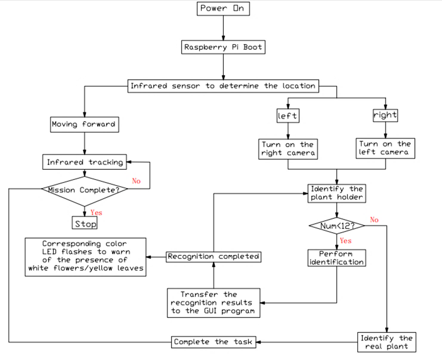
Logic flowchart of detection
Logic flowchart of main program