
Basic Network Communication and Modes
Published:
In multi-robot systems and distributed robotic platforms, reliable network communication is a foundational component that directly affects system scalability, coordination efficiency, and robustness. Practical deployments often involve a combination of routers, switches, wireless links, and multiple network modes, each serving different roles within the overall architecture. This post provides a concise overview of common router operation modes, the concept of uplinking, and how these networking principles are applied in a real-world robot swarm communication setup. The focus is on building an intuitive understanding of data flow, network boundaries, and design trade-offs, rather than on protocol-level theory, making it suitable for robotics researchers and engineers who need to design or debug distributed robotic networks.
Router Modes
Routers generally support 3 primary network modes depending on the context and configuration. These modes determine how the router interacts with the network and connected devices:
Router Mode:
The standard mode for a router, where it acts as a gateway connecting a local network (LAN) to an external network (WAN, like the Internet).
It assigns IP addresses to devices on the LAN using DHCP and performs NAT (Network Address Translation).

Access Point (AP) Mode:
Used to extend an existing network by acting as a wireless access point.
The router disables its DHCP server, and devices connected to it share the main network’s IP range.

Repeater/Extender Mode:
Boosts the range of an existing wireless network by repeating the signal.
It connects wirelessly to the primary router and extends its signal for better coverage.

Some advanced routers may also support additional modes like:
Bridge Mode:
- Allows the router to act as a bridge, connecting two networks without performing NAT. Useful for avoiding “double NAT” issues in complex setups.
Mesh Network Mode:
- Found in modern mesh systems, this mode allows multiple devices to work together to provide seamless coverage across a large area.
Modem Mode:
- Available on some routers with built-in modems, where it acts purely as a modem, passing the Internet connection to another router. Depending on the router model and manufacturer, the terminology or exact features might vary, but these are the common network modes.
Uplink
Uplinking refers to the process of connecting a network device, such as a router, switch, or hub, to another network device or higher-tier network infrastructure, typically to expand or interconnect networks. It is most commonly used in the context of switches and routers.
Key Concepts of Uplinking:
- Switch-to-Switch Connection:
- When connecting two switches, the uplink port on one switch is used to link it to the other switch. This expands the network by enabling devices on one switch to communicate with devices on the other.
- Router or Switch to ISP:
- The uplink port on a router connects it to the modem or an ISP’s network, allowing data to flow from your local network to the wider internet.
- Special Uplink Ports:
- Uplink ports are typically pre-configured to handle the crossover of signals. They eliminate the need for a crossover cable when connecting similar devices (e.g., switch to switch or router to router).
- Direction of Data Flow:
- While “uplink” generally implies an upward or higher-tier connection, it often involves bi-directional data flow, supporting both incoming and outgoing traffic.
Common Usage Examples:
- Connecting a Switch to Another Switch: To expand the number of devices that can connect to the network.
- Connecting to a Modem or ISP Gateway: To provide internet access to a local network.
- Data Center Interconnections: Uplinking switches or routers to aggregate or core switches for higher bandwidth and better performance.
Uplinking is a crucial concept in network architecture as it facilitates scalability and hierarchical structuring of networks.
Our Robot Swarm Network and Communication Design
Detailed Explanation of Uplinking in Our System:
- What is Uplinking in Our System?
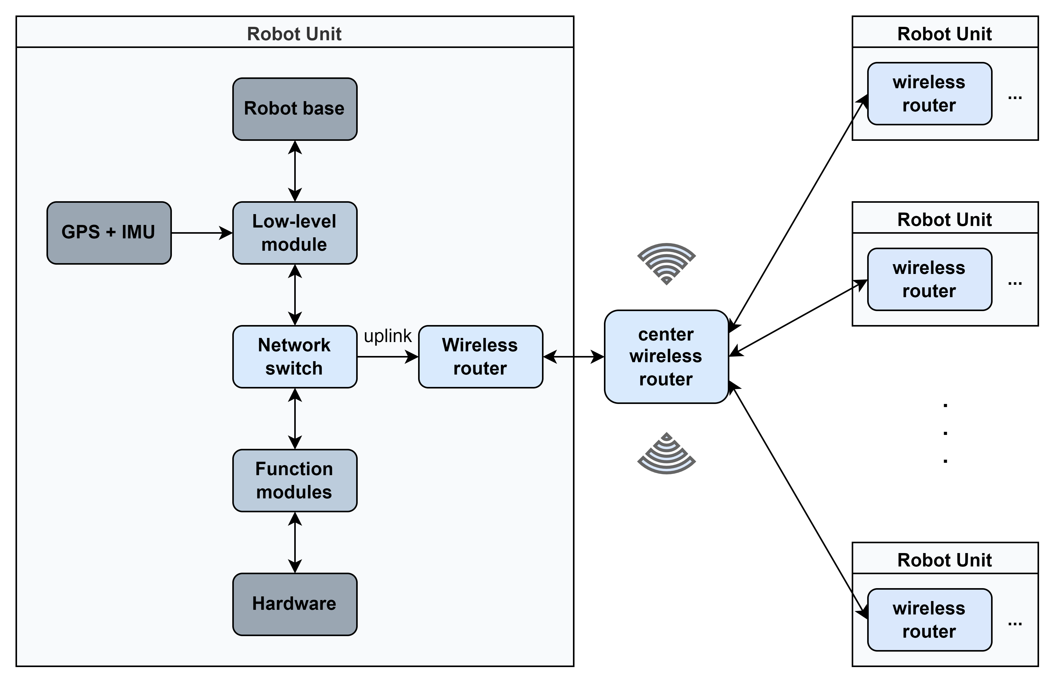
- Uplinking in our system refers to the connection between the network switch inside each robot and the wireless router mounted on the same robot.
- This uplink enables devices connected to the switch (e.g., GPS + IMU, low-level module, and functional modules) to communicate with external networks via the router.
- The uplink also serves as a bridge between the robot’s internal network (LAN) and the central wireless network (WAN) shared by all robots.
How Uplinking Works in Our Setup:
Step 1: Internal Device Communication (Robot LAN)
- Devices Connected to the Switch:
- GPS + IMU, low-level modules, functional modules, and hardware communicate within the robot using the network switch.
- These devices exchange data locally at high speed over Ethernet, using Layer 2 switching (MAC addresses) for efficient communication.
Step 2: Switch to Router Uplink
- Connection:
- The network switch connects to the wireless router’s LAN port via an Ethernet cable.
- The router uplink port acts as the gateway, forwarding the robot’s internal traffic to the robot’s router and beyond.
- Purpose:
- This uplink allows devices on the robot’s switch to access the wider wireless network and enables communication with the center wireless router.
- Network Address Translation (NAT):
- The router typically uses NAT to map private IP addresses from the robot’s LAN (assigned by the switch) to the public IP address used in the wireless network.
- Example:
- GPS (IP: 192.168.0.101) → Router NAT → Public IP: 192.168.1.10.
Step 3: Router to Center Wireless Router (Robot-to-Network Communication)
- Connection Type:
- The wireless router on each robot connects to the central wireless router over Wi-Fi.
- The router acts as a wireless client in this network.
- Traffic Flow:
- When devices on the robot need to send data to other robots or a central server, the data passes from the switch → router → central wireless router → target device.
- Similarly, data coming from the center wireless router is forwarded to the correct device on the robot via the router → switch → target device.
- SSID and Security:
- The robot’s router connects to a central wireless router using a preconfigured SSID and passphrase.
- WPA2/WPA3 security ensures encrypted and secure communication.
Step 4: Communication Between Robots
- Path:
- Data between robots flows through the central wireless router:
- Robot A sends data from its switch to its wireless router.
- The wireless router forwards the data to the central wireless router over Wi-Fi.
- The central wireless router determines the destination (e.g., Robot B) and routes the data accordingly.
- The data is sent to Robot B’s wireless router, which forwards it to the target device via its internal switch.
- Data between robots flows through the central wireless router:
- Example Use Case:
- Robot A’s GPS sends its location data to Robot B for collaborative navigation.
Key Protocols and Configurations in Our Uplinking System:
- DHCP (Dynamic Host Configuration Protocol):
- The router on each robot likely acts as a DHCP server, assigning IP addresses to all devices connected to the internal switch.
- The central wireless router may assign an IP address to each robot’s router for communication in the central network.
- NAT (Network Address Translation):
- Each robot’s router translates internal IP addresses (e.g., 192.168.0.x) to a public IP (e.g., 192.168.1.x) for external communication.
- This prevents conflicts and ensures that multiple robots can connect to the central wireless network without overlapping IPs.
- Routing:
- The central wireless router maintains a routing table to forward data between robots or to a central server.
- Wi-Fi Client Mode:
- Each robot’s router is configured in client mode to connect to the central wireless network.
Data Flow Example in Our System:
Let’s trace a real-world example:
- Scenario
Robot A wants to send its GPS location to Robot B.
- Step 1: The GPS module sends data to the switch on Robot A.
- Step 2: The switch forwards this data to Robot A’s router via the uplink.
- Step 3: Robot A’s router sends the data over Wi-Fi to the central wireless router.
- Step 4: The central wireless router routes the data to Robot B’s router.
- Step 5: Robot B’s router sends the data to its internal switch, and the GPS module on Robot B receives it.
Potential Challenges and Considerations:
- Network Congestion:
- Multiple robots communicating simultaneously could congest the central wireless router.
- Solution: Use a mesh network or distribute robots across multiple access points to balance load.
- Latency:
- Uplinking and routing introduce slight delays, especially with multiple hops.
- Solution: Prioritize critical traffic using Quality of Service (QoS) settings on the central wireless router.
- Coverage and Signal Strength:
- Wi-Fi coverage might be insufficient for large working areas.
- Solution: Use range extenders, additional access points, or a mesh network.
- IP Address Management:
- IP conflicts could occur if not managed correctly.
- Solution: Use a consistent IP scheme (e.g., 192.168.0.x for local robot LAN, 192.168.1.x for the central network).